So, Zelda Breath of the Wild. If my count is correct, I had already done 3 playthroughs on my friends' consoles, but it wasn't enough, I wanted to try it again on Cemu. But I'm not settling for anything but the best gaming experience, and I wanted the gyroscope features too, which of course was not available with my cheap-ass controllers...Worry not, I have a plan.
Cemu has an interface that can receive motion control data from UDP packets using a custom protocol. Normally, people use this to feed Cemu with data from their phones, PS3 controllers, etc. So I could use one of my old PS3 controllers and play the game... But that was too easy, so I decided I would use an Arduino and a MPU9250 IMU module glued to my controller to send data to my computer through the serial interface, on my computer I would run a program that would read this data using a custom protocol of mine, and convert it to CEMU's UDP protocol. Now that's the ultimate gamer maker experience.
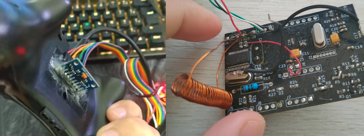
And so I did! With the help of a level shifter to lower the voltages from the Arduino to the MPU9250, I could successfully play Zelda again, on Master mode nonetheless! Check out how this improvised version ended up looking like:
I just dumped the code on my Github, It's been a while since I made this proof of concept, so I don't remember the details on the code, I will just give out the general ideas:
I used the MPU-9250 arduino library, however it returned values in floating points, and applied calibration compensation in most values. Since Arduino doesn't have a FPU, floating points use double the bytes as compared to the MPU-9250 original data type(2 bytes), and all the data would go to my computer eventually, I edited the library to return the values as raw as possible to obtain higher data rates(hopefully). Calibration also seemed to be kept across power-ons, so I did it once, printed the biases and scales on console, and hardcoded them in the python script receiving the data(receiver.py). This script gets the data, rotate some of them to match the rotation of the controller, crafted CEMU motion control UDP packets, and sends them away.
This was fun and all, I was able to complete the main storyline, but wanted more, specially the master trials, and this setup had lots of flaws... The gyroscope started disconnecting frequently due to bad contacts with jumpers, I had way too much weight on the wire, carrying the Arduino and everything, having 2 cables is awkward... So I decided to make a v2!
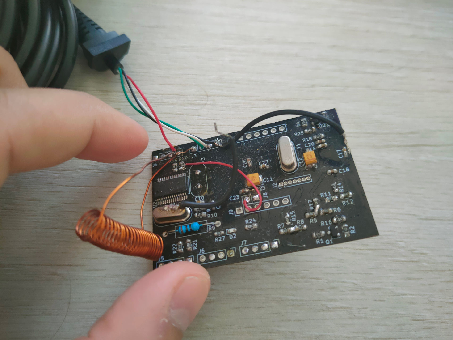
Here was my ideia: I would design a PCB that would integrate the gyroscope, a level shifter, an ATMEGA328, a USB-serial converter, and to top it all off, a USB Hub. The ideia is that I would cut the controller usb cable and connect it to the hub in the PCB, which would as connect the serial converter talking to the Arduino, and so only one cable had to travel to the computer. Having everything on the PCB would solve all my problems with bad connections if I soldered well enough, and if I made the board small enough, I could maybe fit it inside the controller. Also, I wanted to make the board very modular. Skip the USB HUB circuit, and you have an arduino with integrated gyroscope. Don't solder the arduino and everything ahead, you have a plain USB HUB. skip the gyroscope, everything still works.
So I started to design the board, but I made the first mistake very early on... I decided to make it cheap, and get questionable components, from questionable sources. A USB Hub IC on aliexpress with a kinda short datasheet, CH340 instead of FT232, MPU-9250 from the cheapest aliexpress seller... Getting stuff from aliexpress is easier for me since I'm in Brazil, but it was not worth it. Later some friends told me about better, and still cheap suppliers, but the damage was done.
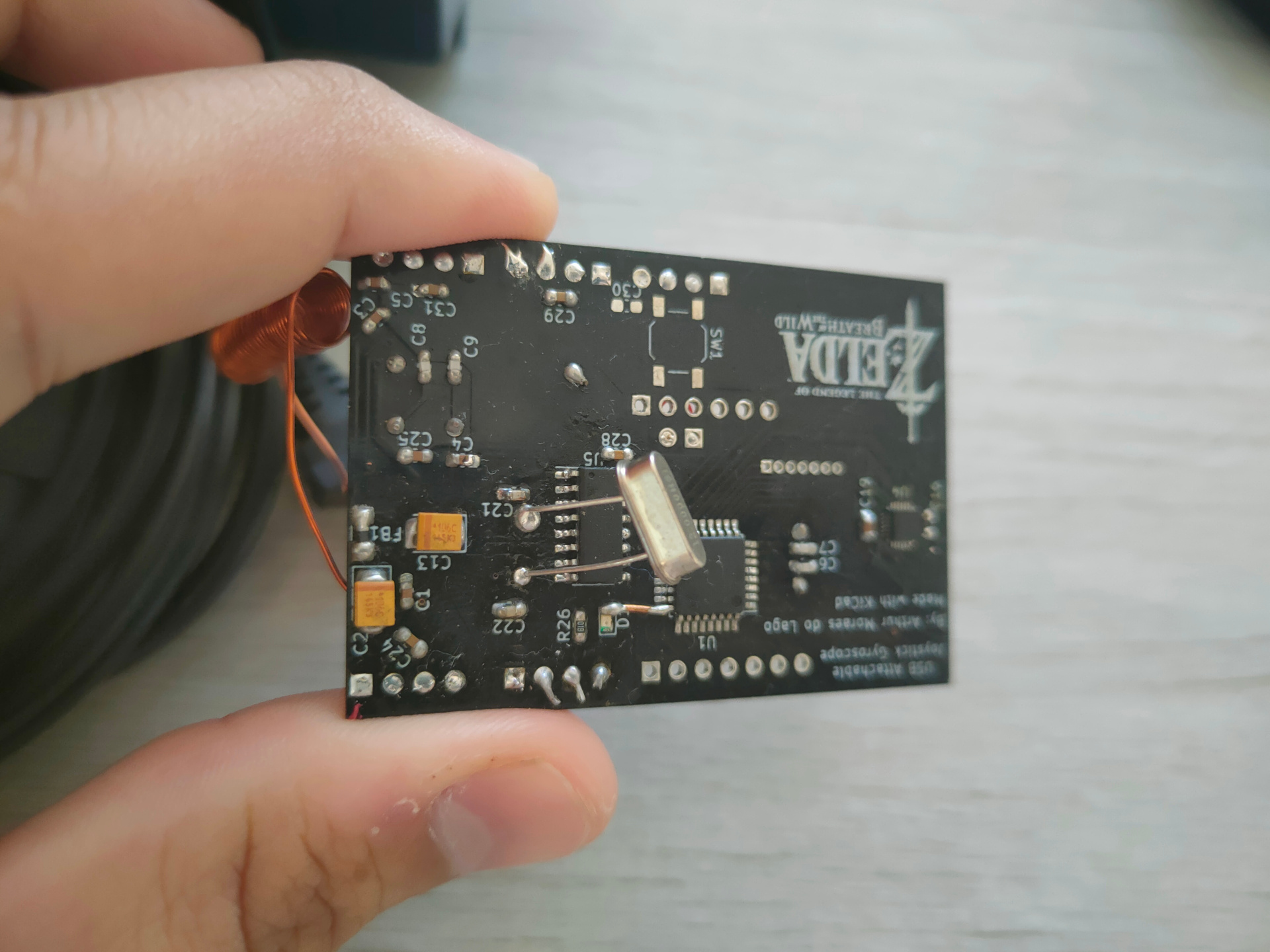
I designed the board, it's in the same github as the code, under the "placa" directory(you can open it with kicad, it's free and "libre" software). I based the usb hub part on this project to make sure I didn't forget anything. This is how the board turned out after finished the design, and after production(I sent it to be manufactured in china too, paid double what I expected due to import taxes, but still managed to keep the price bellow national companies unfortunately, since they required me to get a whole panel of boards).
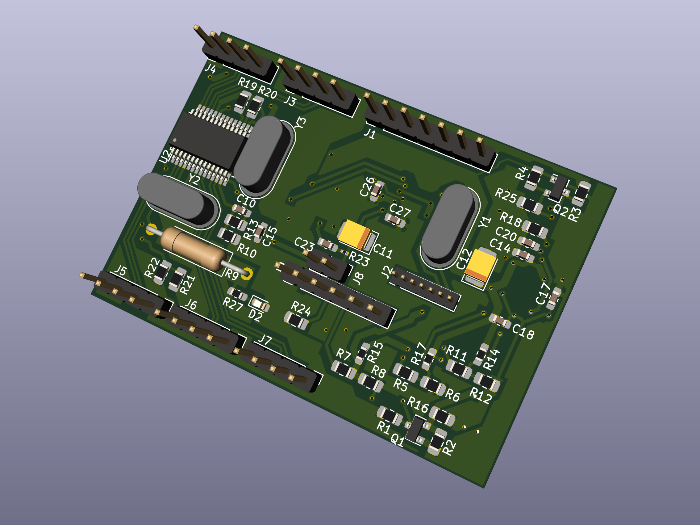
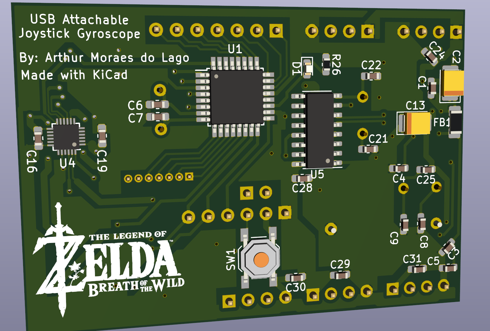
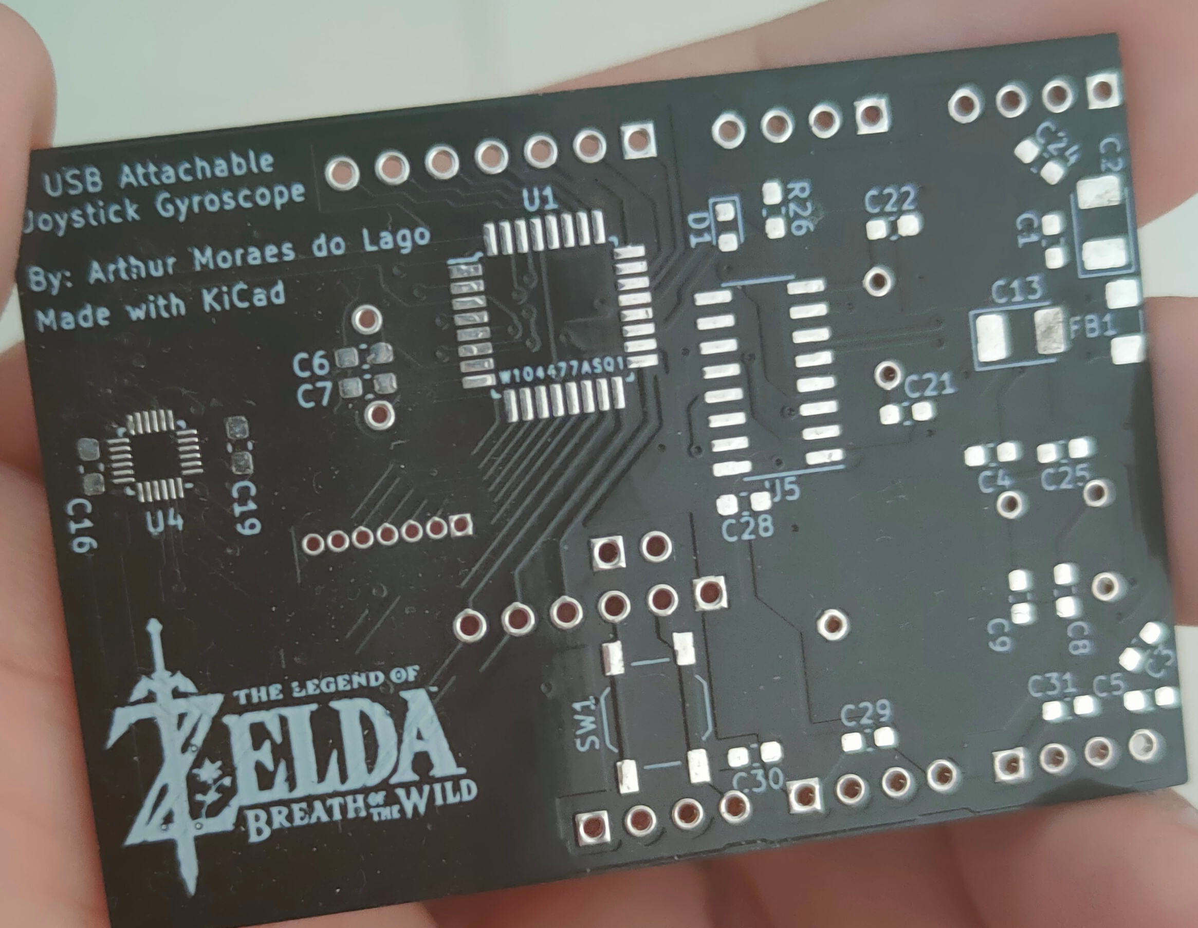
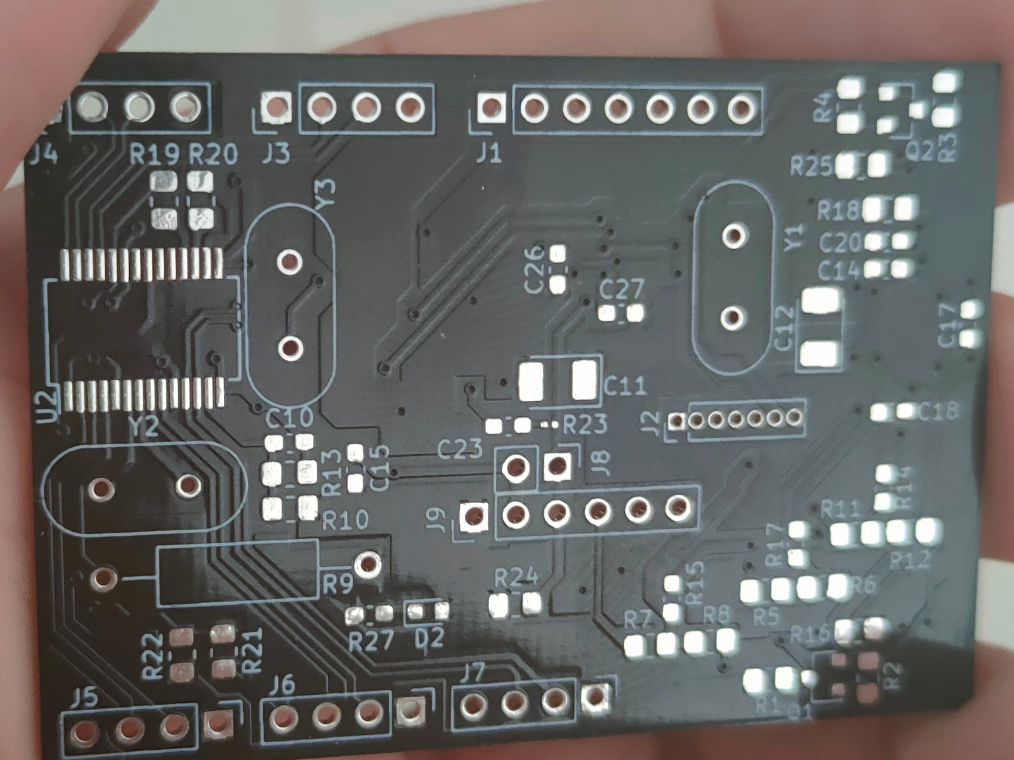
Most beautiful thing I made in my life, but you may already be cringing about the design flaws, but don't worry, I'll mention them myself:
I work with RF at my job, 2GHz minimum, I knew that high frequencies invoke all kinds of black magic, and should not be taken lightly. When I was designing circuits for 8MHz, I thought that this was manageable, and was very liberal when making the layout... Boy was I wrong. All the time, touching the crystal, or some part of the circuit, would make the board stop being recognized in the computer, and wouldn't come back. It was overall super inconsistent, any slightly higher current would also make everything stop working. Having one less crystal would already justify the extra cost of the FT232 over the CH340. One of the USB lines is also a big mistake. I thought I could have the option to have an extra USB port available in case the CH340 wasn't soldered, and left a giant open ended line on the board... I don't understand reflection, but I know it exists, and is probably one of the reasons communication was so unstable.
The USB Hub was the flakiest of all... I switched it a couple times, and it hardly ever worked consistently, but was ultimately the main reason I gave up on the board. It has a pin indicating if the HUB is self-powered or outside powered. To my surprise, if it was set to self-powered, it would advertise low currents to the USB joystick, which made it not even try to turn on... If I set the pin to outside power, instabilities intensified A LOT, and I couldn't get the computer to recognize the HUB and joystick. Datasheet doesn't say much... Next time, I will just get a more expensive, common and well documented component, probably copy from another project(although I already did this with this board, no idea how that guy made this work, my schematic is equal to his).
I also may have underestimated the importance of some inductors, but adding them externally didn't solve much either, so I'm not that worried.
I was told the ground plane wasn't much useful the way I did because it had some narrow regions. It is basically 2 ground planes, but I tried my best to lower the resistance between these two making thicker lines, and having more than one path to one another, but it might no have been enough.
My choice of suppliers was probably the most frustrating. I got 5 MPU-9250's. Every single one of them had some kind of defect, be it a random gyroscope channel not working, or straight out no responding SPI communication. After trying all five I had bought, I decided to rip one out of a breakout module I had lying around, and it worked flawlessly from the beginning... It could be that I fried the first five with my hand soldering... But then I could remove one from a breakout board, solder it to my board, and it works perfectly? What are the odds?
I another questionable decision was doing the level shifter for the gyroscope from scratch using MOSFETs. I got a little carried away, and thought it would be a cool learning exercise, but this was no place to go experimenting when it's so expensive to produce and import these boards. The shifters worked well(but If I remember correctly, I had to reduce the SPI frequency), but took a little while to solder and occupied a big chunk of the board(which could have been used to improve ground plane and reduce board size), next time, I will just use a dedicated IC for this.
I still think I got some things right, like every IC's supply voltage line has a capacitor nearby to lower noise(we had problems with this in the robotics team, motors interference would straight up turn off the MCU before we patched some stuff, will never forget this lesson). I made the most challenging solder(MPU-9250) a bit easier to manage by manually editing the footprint and giving it longer pads.
At some point, about the time I was soldering the third board hoping I had faulty components on the first two, I gave up on it, I'm currently waiting for inspiration to scrap and redesign everything with higher quality components, and not underestimating MHz frequencies.
Here's the final result, after all the workarounds I tried: