FPGAs were always part my interests, ever since I discovered them in university, I never failed to be amazed at "prototyping silicon chips". Doing work interfacing with them daily at my job also helped me remember how cool they are. So it was just a matter o time before I actually bought one and started playing with it at home.
However, I wanted to do it the hard way. Ever since I had to power on, program, and prototype with a Kinetis MK06 at the Phoenix Robotics Team, it downed on me that development boards are just convenience. I can save a buck by doing the hard work they do and still learn in the process. So I decided I would try to buy chips directly from digikey, solder them on an LQFP adapter to through hole pins, use jumpers to provide necessary signals and supplies, and find out about programming protocols.
Deciding on which chip to use then, followed this criteria:
- Has to be cheap(I was kinda broke at the time)
- Free to use design tools, preferably available on linux(even better, with open source alternatives available)
- Has to be a package that I can hand solder(any LQFP, even QFNs maybe, probbly not BGAs)
- Needs to have some kind of embedded RAM memory for the project I wanted to do(more on this later)
I probably didn't spend enough time make this decision, not nearly as much as spent on previous hardware choices, but ended up happy with my decision. I decided on the Lattice MachXO2 2000HC. Lattice tools are available on Linux, I seem to recall seeing someone going a long way with purely free software tools with one. This model had all the peripherals I deemed necessary at the time, so off we go, bought some from digikey, patiently waited their arrival, and set out to solder them.
It wasn't an easy solder for me at the time, but this chip specifically taught me a lot, and brought me to the next level in soldering. Namely, it was the first soldering job I just couldn't do with cheap flux, I had to buy professional grade stuff to get things to work, but with the right tools I quickly got the hang of it. Butchered some 2 or 3 pins while learning, but it's Ok, they were just IO.
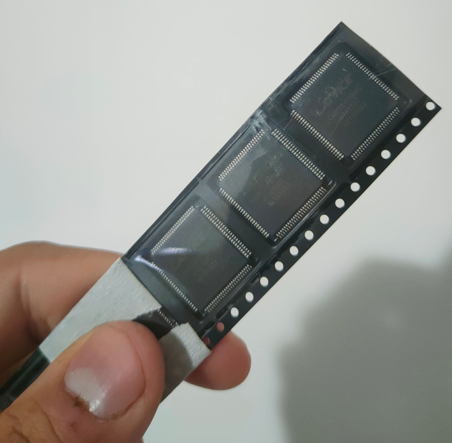
The FPGAs as I received them, really just the IC 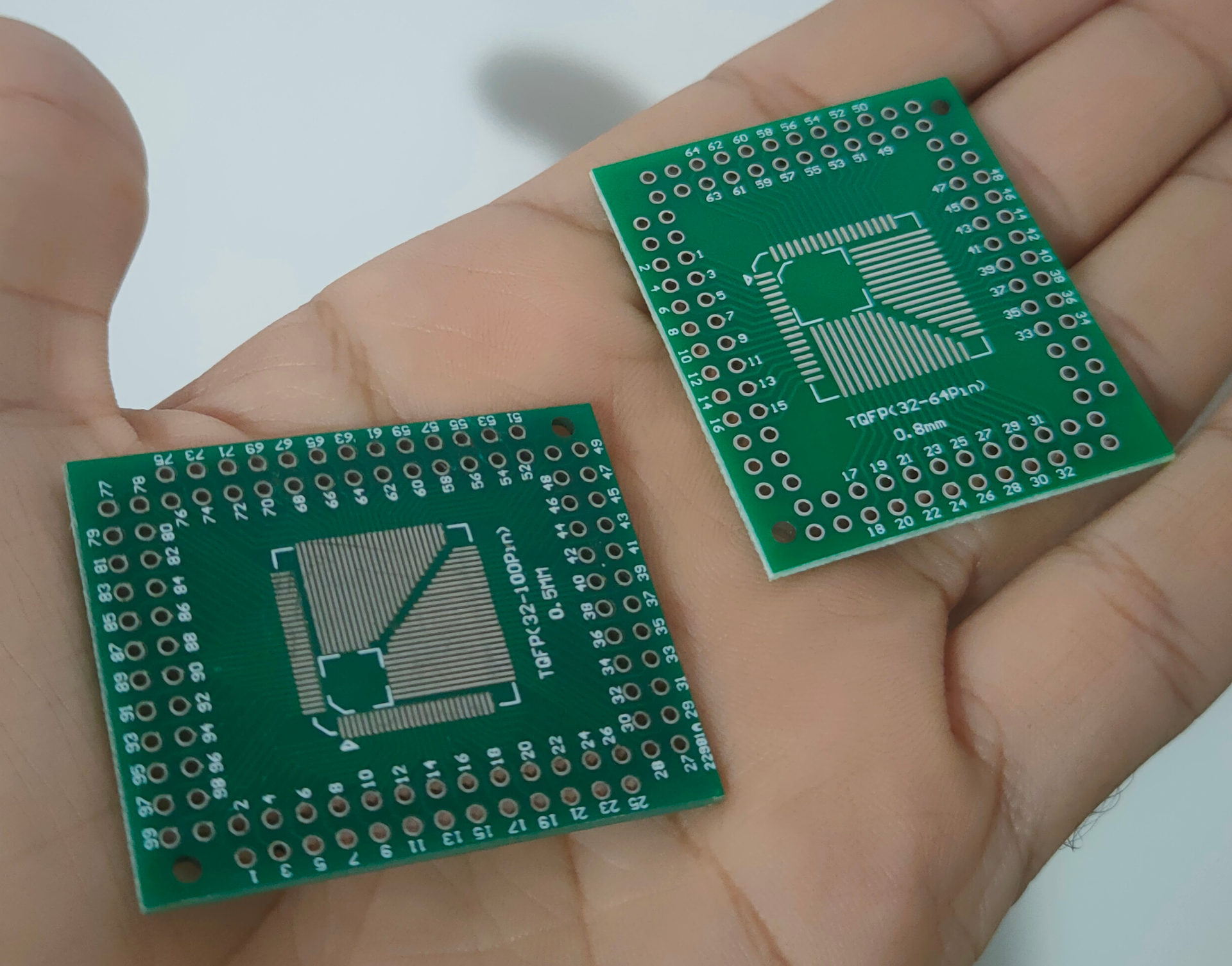
The adapters I have to solder the FPGA to to be able to work with jumpers 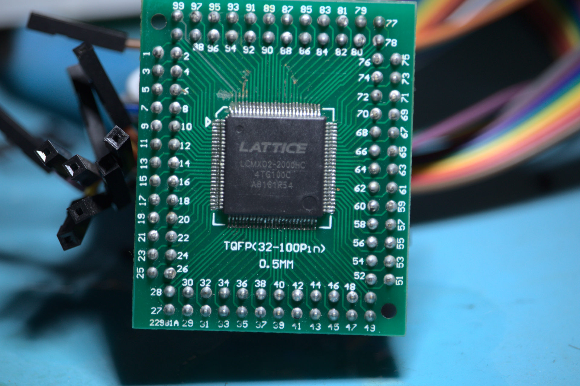
Soldering job done, this is the final result. Some pads gone on upper left corner, but they didn't matter
Not perfect, but I'm pretty proud of the result
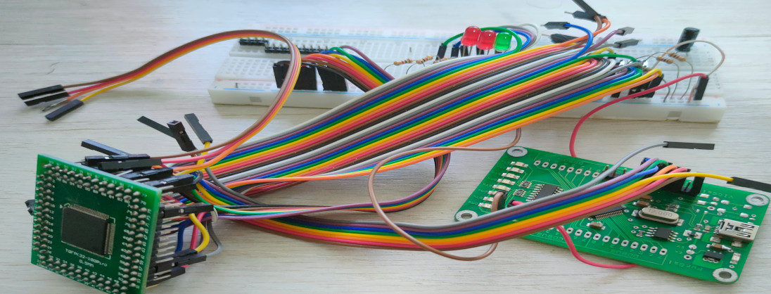
For programming, I was very happy to find out that I already had a suitable programmer:
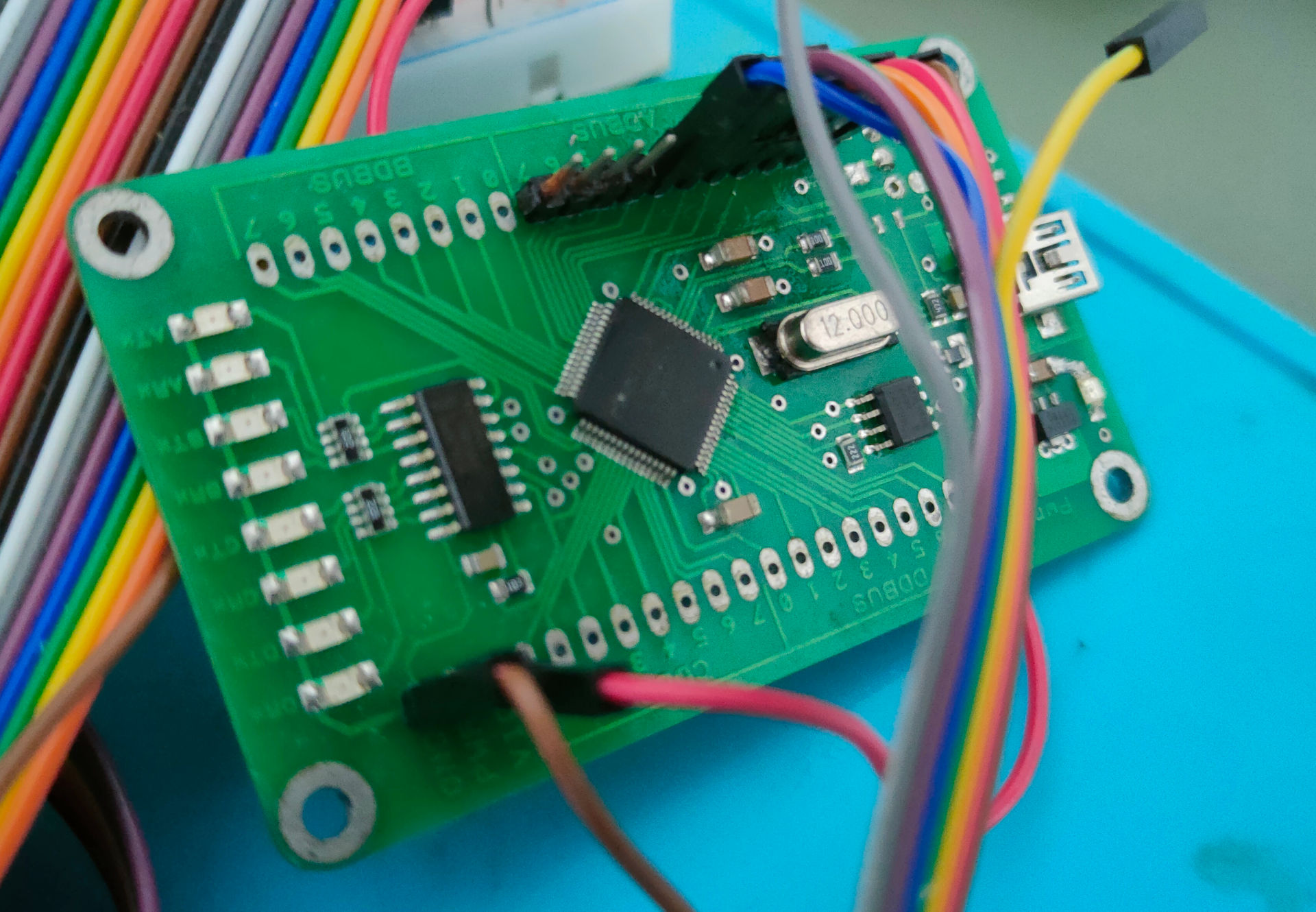
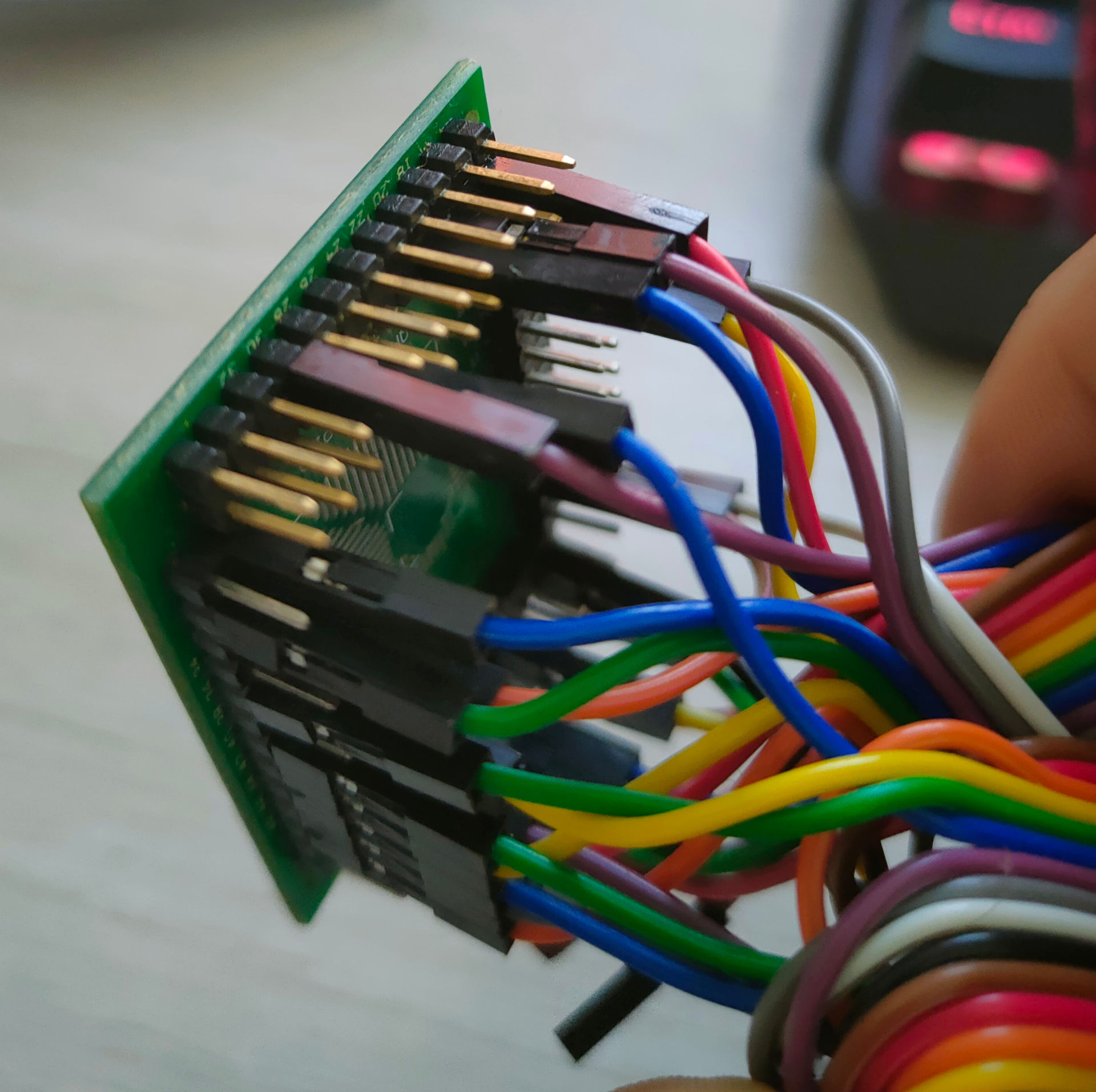
Lattice FPGAs can be programmed from Diamond(their EDA tool) using an FT2232 for JTAG interface, and I already had this breakout board from another project, interestingly enough, very related to JTAG too(it was actually for SWD). Lattice even provides app notes with instructions on how to wire the chip. I thought I found a blog post somewhere that used the exact same board as me, but couldn't find it anywhere, but the wiring doesn't seem hard. If anyone had the same idea as me, and is having trouble with the wiring, hit me up, and I can check how I wired it to get it working.
Everything went somewhat smoothly, I got to program it without any major problems. Real trouble appeared for actually designing stuff... Free software simulator GHDL giving different results from the real world and Diamond's included simulation tool, weird interfaces for integrated peripherals, learning to setup simulations, simulations that are no longer distributed freely, and many more... I will not discuss these things in this post, because I'm still battling some of them, but probably in the future.
Before showing things actually working, I want to talk about the project I chose to make first. I fell in love with the idea of smart LEDs such as the WS2812B. A brief explanation in case you never head of them:
These tiny LEDs have mainly 4 pins, ground, power supply, Data In and Data out. There is a tiny IC inside the chip that can interpret and transmit a very clever protocol suitable for driving long chains of LEDs. In this protocol, we send rectangular waves to the first LED in a chain. We encode 1's and 0's by sending the rectangular wave with a specific time on HIGH and anothe specific time on low(namely, 0.8us on HIGH, 0.45us on LOW is interpreted as a bit 1, and the opposite is interpreted as 0). The LED reads 24 waves from the data in pin, for the 24 bits necessary to determine it's color(8 bits for each component, RGB, classic). Now here's the magic: After an LED reads the 24 bits it needs, it ignores the following waves, but re-transmits it on the data out line. The next LED in the chain will consume the first 24 bits it sees, which are actually the second group we sent out, and re-transmit the rest, and so on. When the data in line stays LOW for an extended period of time, all LEDs are reset and will consume the next 24 bits it sees. This really cool protocol could theoretically drive gigantic chains of LEDs, and we could precisely control the color of each individual LED without spending hundreds of wires to each of them. I find this geinous.
Ok, so the protocol is really cool, and people have drive these LEDs in many different ways, Arduinos on bitbang, Arduinos using the serial interface, raspberry Pi using audio interface, etc. But I wasn't really happy with them, because on the arduino for example, we have to spend use our main function constantly waiting the timings and driving pins, we are left with too little time to do other processing, like reading new colors from somewhere else. I couldn't get over how a simple timing protocol would take so much processing. Enter FPGAs: making this protocol on an FPGA is so simple and consumes so little resources, basically a counter gets everything done. SO I wanted to make a WS2812B driver that would receive configuration from some simpler serial protocol(I2C? SPI? some simple UART thingy?), store it in RAM, and constantly read from it to update LEDs.
To show off how easy this protocol is on an FPGA, I made a block that receives a signal, and constantly encodes it with the set timings on the first day that I actually designed stuff, I showed it off in this video:
The little wire I manually put on and off the protoboard drives an input pin on the FPGA HIGH, while it is normally pulled down. I designed a simple counter that drives a pin HIGH or LOW on some thresholds, and these thresholds are determined by the state of the input pin, so I can encode the state of the input pin with the WS2812B protocol. Very simple stuff, obvious not suitable for actual use, but it's a first step.
I hope the next blog post I talk about the FPGA, I will have fully function driver that is easy to communicate, but I still have a lot of good practices to learn to actually make something good, but we'll see what I can do.